Description
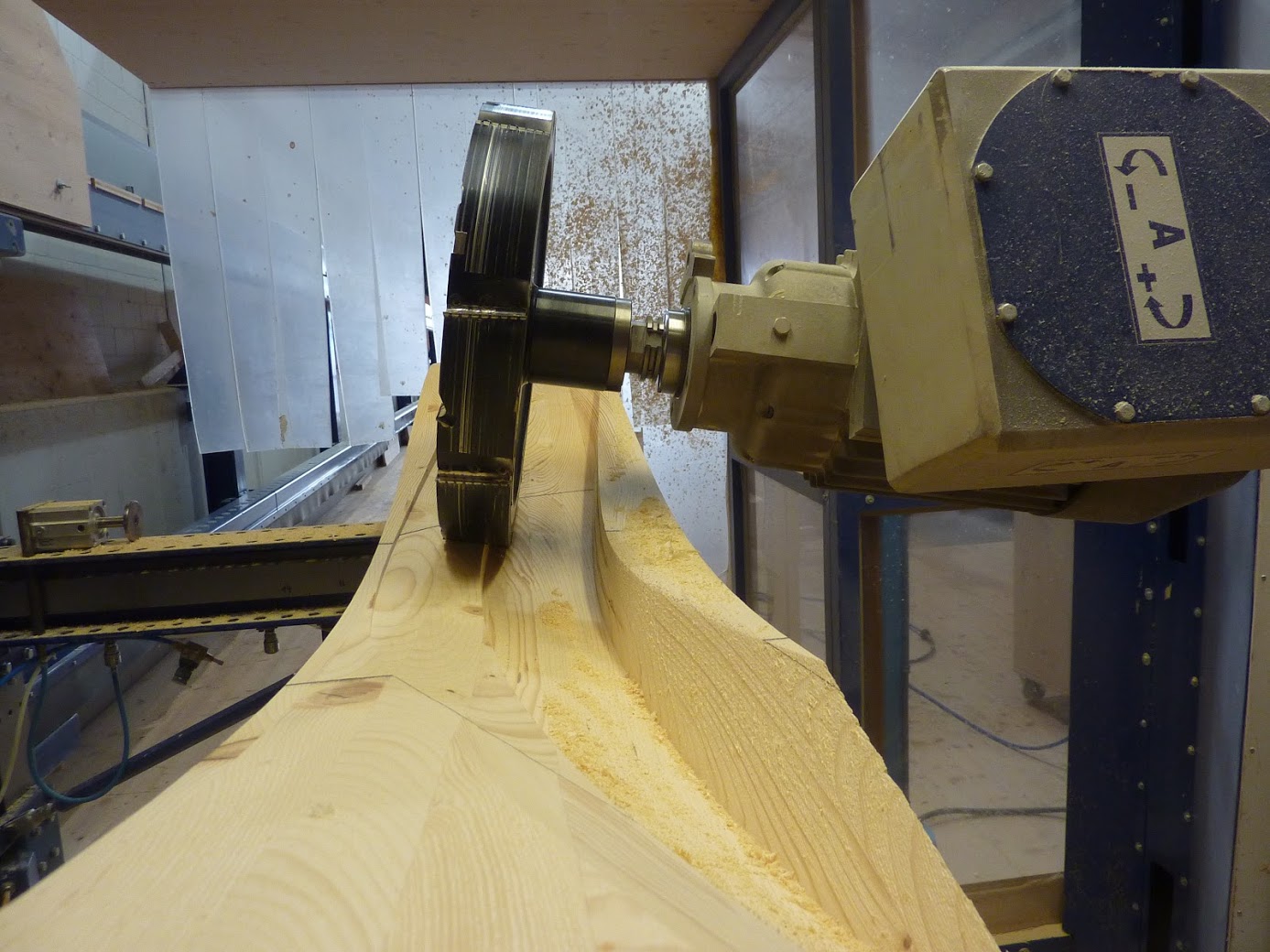
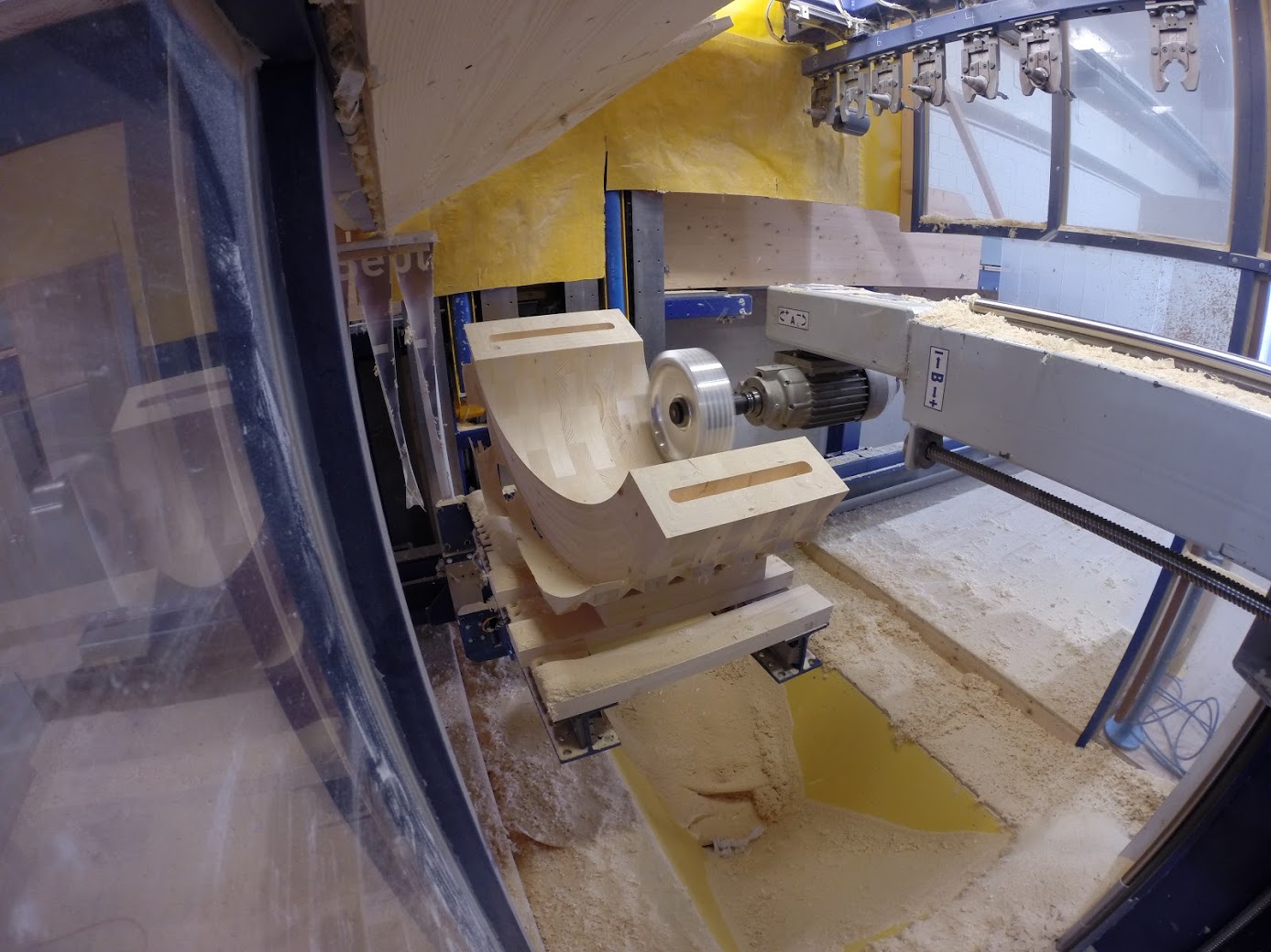
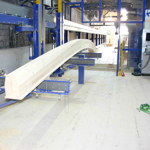
Free-form machining at its finest
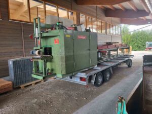
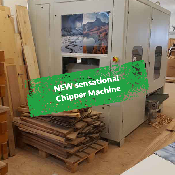
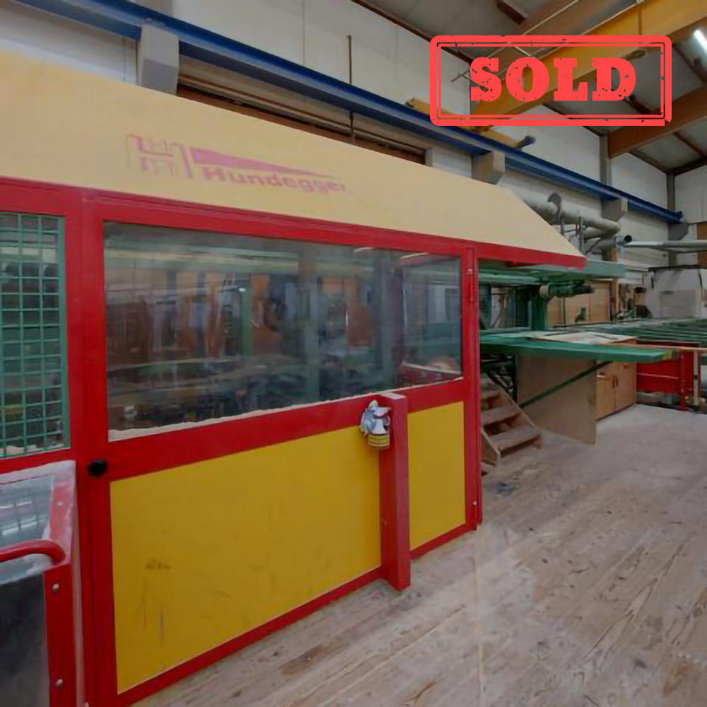
The photos show sample photos of the system!
Machining center for high-quality timber engineering, carpentry, special joinery, prefabricated house and element construction.
We are currently offering a second-to-none Krüsi joinery system.
Complete with tool magazine, track system, and 6 clamping carriages.
Maximum cross-section that can be machined from 6 sides without turning:
approx. 1400 mm in the Y axis x approx. 1200 mm in the Z axis, up to a length of approx. 28 m
A- and B-axis drive with Wittenstein / Alpha Robot gearbox
With rigid rail guides for the clamping carriages.
Space requirements:
Total length of the machine system – 46,000 mm
Total length of the guideway – 45,000 mm
Total height of the machine system including protective hood – 3,520 mm
Total width of the machine system – 6,600 mm
Machine system with protective cabin and light barriers including control cabinet complete with
control system without joinery program. (On request)
Simulation and collision monitoring
Collision monitoring on the machine
Technical processing with electrical diagram,
PLC software, CNC software, and documentation
in German.
General technical description of the machine
LIGNAMATIC:
Total length of the machine system: 46,000 mm
Total height of the machine system including protective cabin: 3,520 mm
Total width including protective cabin: 6,600 mm
Sold ex-site as is without warranty or guarantee.
Costs for disassembly, packaging, loading, transport, etc. are not included in the purchase price.
Payment immediately upon receipt of the invoice without deductions.
The facility can be viewed at any time by appointment.
Available from approximately December 2025 / January 2026
Basic Elements
The stable and heavily built machine stand is welded from steel and, due to its hollow body, is highly torsion-resistant. It is precisely machined at the necessary points and features bolted, continuously supported, hardened, and ground precision round steel guides (Ø 40 mm), on which the cross-guide support with an arm is held and guided (Z-axis guide). The counterweight for the arm with the milling motor is suspended by two heavy precision link chains. It is fully protected and safely housed within the hollow body of the machine stand. The load is redirected via two large chain wheels.
The cross-guide support is made from a special aluminum cast alloy due to its weight. To maintain the stand’s stability, it is designed with thick walls and strong ribbing. The cross-guide support is equipped with six radial ball-bearing guide bushings vertically and four horizontally, ensuring high load capacity and rigidity.
The arm is manufactured from a square steel hollow profile and reinforced with welded-in supports. It is precisely machined at the necessary points. It is held and guided in the radial ball-bearing guide bushings of the cross-guide carriage by two continuously supported, tightly bolted, hardened, and ground precision round steel guides (Ø 40 mm). As a result, the arm can move smoothly and backlash-free at high speed across the entire travel range in both Y and Z directions via the cross-guide carriage.
A B-axis is built into the arm and is mounted in large-dimensioned guides. It mainly consists of a large, tubular hollow body. At one end, a mounting housing for the A-axis is attached, which ultimately holds the main spindle motor pivotable in all directions. At the other end, a torsion-resistant special coupling for connection to the B-axis drive is installed. The A and B axes are driven and mounted using Harmonic Drive robot motor-gear units.
Axis Drives
The cross-guide support, including the arm, is driven in the Z direction by a state-of-the-art AC servo motor with a holding brake and built-in absolute resolver. Power transmission occurs via a toothed belt onto a ball screw spindle (Ø 40 mm x 40 mm pitch). This spindle is entirely backlash-free and has a very high efficiency.
The arm is driven in the Y direction by a state-of-the-art AC servo motor with an integrated absolute resolver. Power transmission occurs via a toothed belt onto a ball screw spindle (Ø 40 mm x 40 mm pitch). This spindle is also entirely backlash-free and highly efficient.
The B-axis in the arm is pivotable by approximately 450 degrees parallel to the Y-axis. The pivot movement is executed by a Harmonic Drive robot motor-gear unit. The absolute resolver is mounted directly on the motor.
The A-axis is pivotable by approximately 200 degrees. Its pivot movement is also executed by a Harmonic Drive robot motor-gear unit with an absolute resolver.
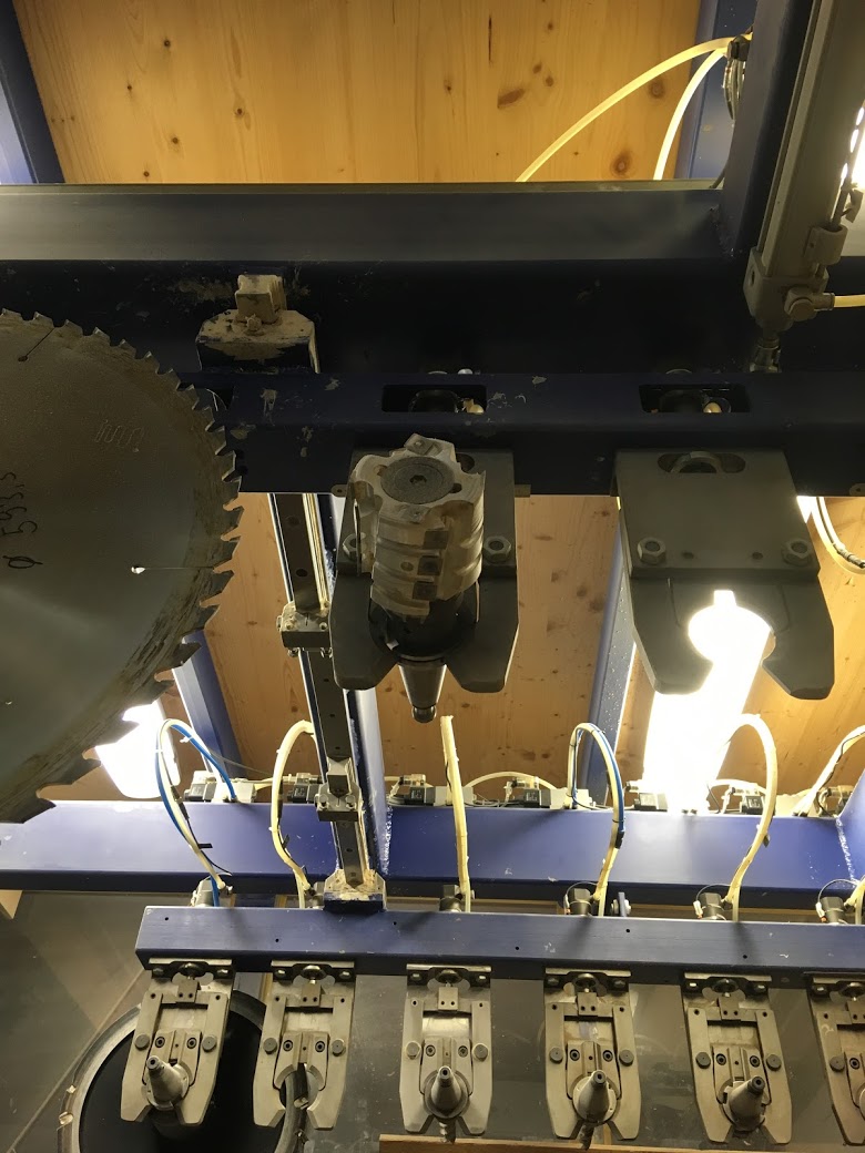
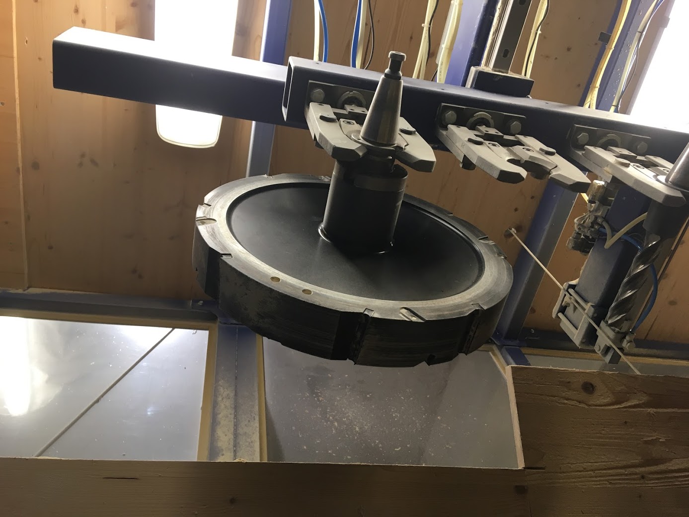
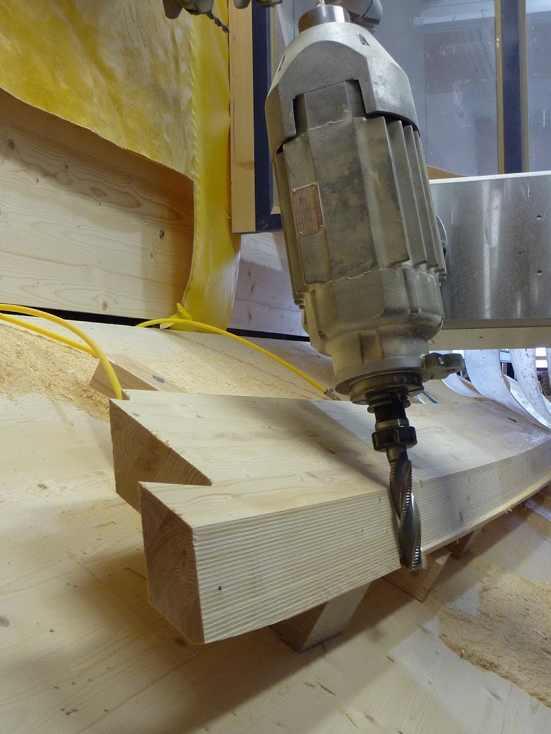
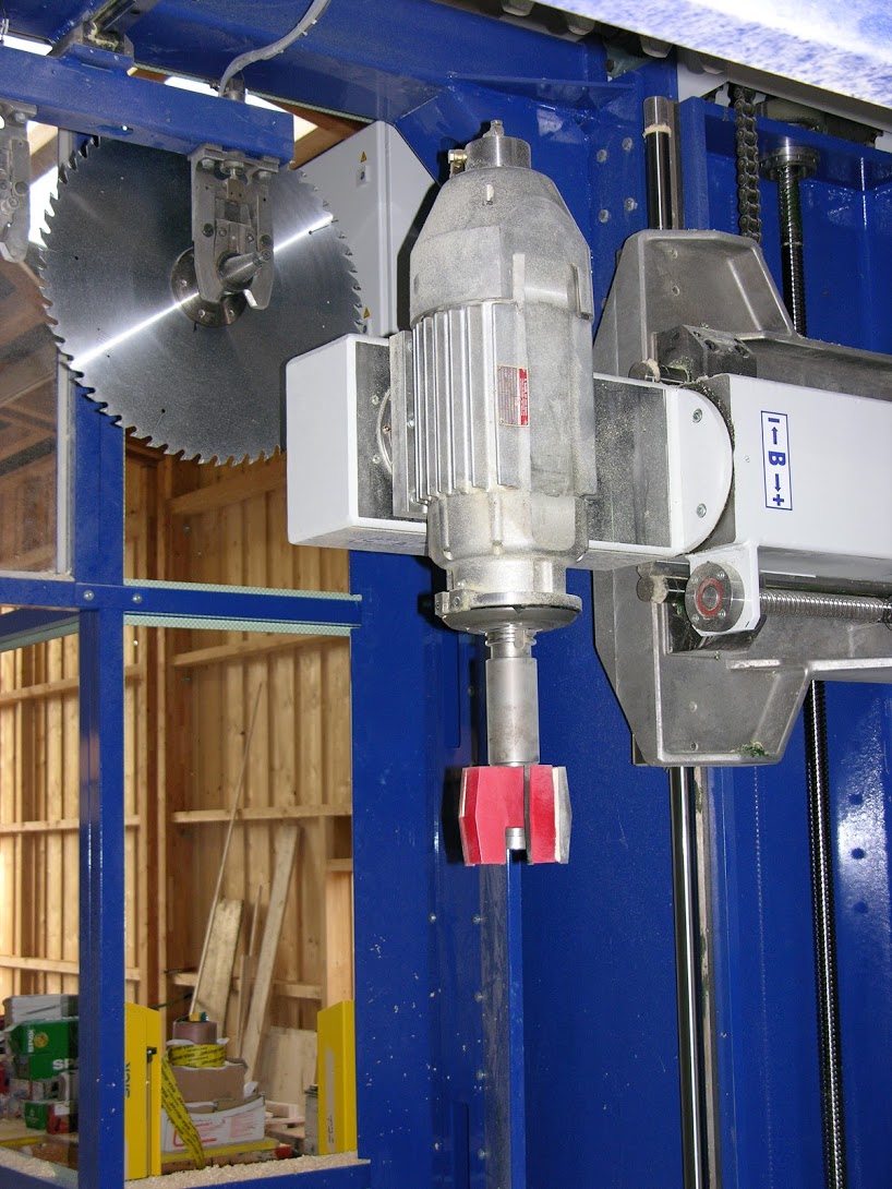
Main Spindle Motor
The winding of the main spindle motor is designed similarly to a standard three-phase asynchronous motor (3-phase AC motor). It is very long in relation to its size but has a small diameter. To enable a wide range of speed regulation, a special magnetic laminated core is incorporated. The speed control is managed by the machine’s control system via an electronic current regulator (frequency converter). The motor shaft is designed like a tool machine’s main spindle and equipped with special main spindle rolling bearings. As a continuous hollow spindle, it is fitted with a steep taper ISO 40 at the front. Inside the hollow spindle, a tool clamping system preloaded by a spring pack is installed, which can be released using a special hydraulic cylinder. This prevents the tool from falling out in the event of power, air pressure, or hydraulic pressure failure. The tool clamping system is equipped with a compressed air channel to blow out the tool cone and the receiving cone in the spindle during tool changes.
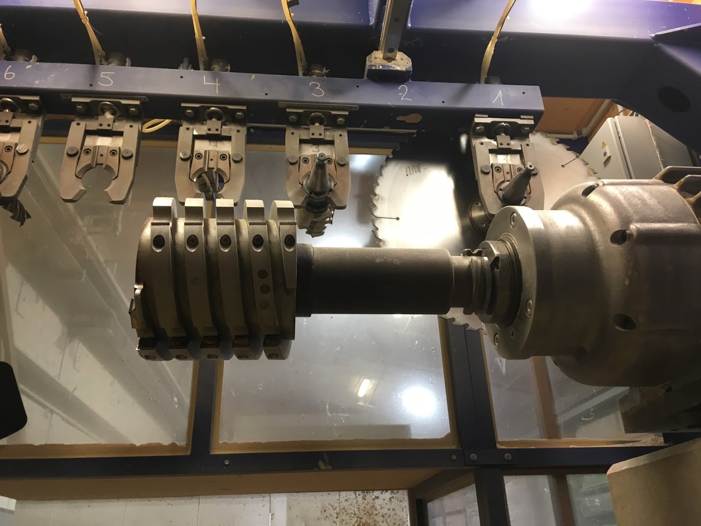
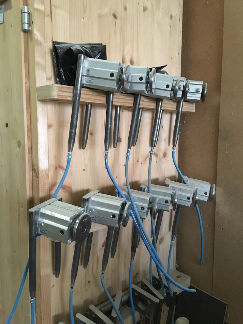
Tool Magazine
The tool magazine is mounted on top of the stand and designed as a double-sided row magazine. The tools are stored horizontally and held by self-locking gripper tongs. These tongs can be pneumatically opened. A total of 15 (16) storage slots are available.
Tool Change (Short Description)
During tool transfer, the corresponding row magazine moves toward the main spindle motor, which is positioned accordingly, and hands over the tool. At the same time, the main spindle motor blows out the tool’s cone.
When taking over the tool, the pull stud is gripped by the clamping unit and drawn in by the disc spring pack. Sensors monitor whether the tool is correctly clamped and held. The machine can even detect if the pull stud is missing from the tool cone. Only then does the gripper tong open, and the main spindle motor moves down with the tool. While machining is in progress, the magazine moves outward. When the tool return command is given, the appropriate row magazine moves back in, and the gripper tong opens. The main spindle motor positions itself in preparation and then moves from below into the open gripper tong. The gripper tong closes, the main spindle motor releases the tool, and the magazine moves out with it. The main spindle motor then positions itself for the next tool.
Practically all movement sequences are monitored by the control system using sensors.
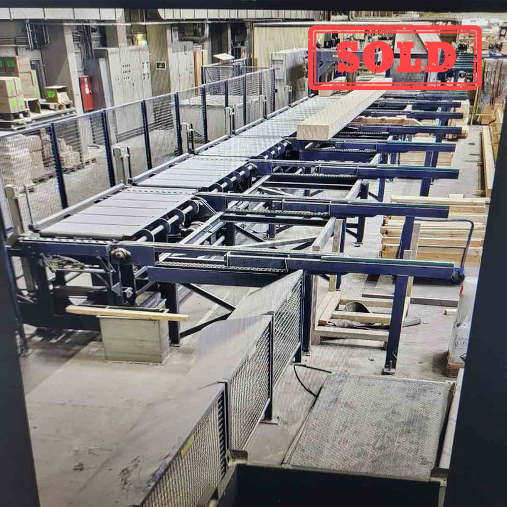
Rail System
The rail system is installed along a concrete wall. Posts made from DIN T-beams are anchored to the concrete wall every 3,000 mm. Extremely strong and secure anchoring is required to ensure the precision of the guideway for years to come.
The upper longitudinal beams, also made from DIN T-beams and precisely machined where necessary, serve as a mount for the hardened and ground precision round steel guide (Ø 40 mm), which is supported and bolted every 200 mm with a saddle. The lower star-profile rail guide is mounted on a special support rail made of square hollow profiles and angle steel. The hardened precision gear rack is absolutely parallel and bolted onto the precisely machined support rail. The guide rails are installed in a way that largely protects them from dust and damage. Along the entire length of the rail system, energy chain guides for the four clamping carriages are installed.
Clamping Carriages
The clamping carriages are held and guided at the top by two linear bearings with super ball-bearing bushings and at the bottom by two guide carriages on the rail system’s guideway. The support arm and the front of the carriage are mechanically precision-machined. Two rows of mounting holes for inserting horizontal clamping cylinders are provided on the support arm.
The pressure beam is motor-adjustable in height via a spindle and can also be swiveled using a pneumatic cylinder. A special toggle joint automatically locks the pressure beam in its swiveled position. A built-in pneumatic cushion in the pressure beam ensures vertical clamping. This allows for simultaneous clamping of workpieces with slightly different thicknesses.
Each of the four clamping carriages is equipped with a state-of-the-art AC servo gear motor with a holding brake and built-in absolute resolver. Power transmission occurs via a hardened gear onto the rail system’s gear rack. Each carriage has two energy drag chains, with power and control cables routed separately to avoid interference from parallel-running long cables.
Hydraulic Unit with Pressure Accumulator
The hydraulic unit supplies the machine with pressure oil to release the tool clamping system in the main spindle motor.
General Information
All moving cable lines are routed in energy chains. Most cables are equipped with multipole connectors on both the machine and control sides. Well-accessible junction boxes with plug connections enable quick troubleshooting of potential contact faults.
Working Area
Total length of the machine system (customizable) standard = 46,000 mm
Total height of the machine system including protective cover: 3,670 mm
Total width including protective cover: approx. 6,600 mm
Length of the guideway X-axis: 45,000 mm
Number of clamping carriages: 6 or 4 units
Max. transverse travel of the boom Y-axis: 1,750 mm
Max. vertical travel of the boom Z-axis: 2,030 mm
Swivel range A-axis: approx. 200 degrees
Swivel range B-axis: approx. 450 degrees
Support width of the clamping carriage: 1,300 mm
Working width Y-axis: 1,200 mm
Height of the clamping beam above support: 0 – 300 mm
Travel Speeds
Rapid traverse speed X-axis: 57 m/min
Rapid traverse speed Y-axis: 40 m/min
Rapid traverse speed Z-axis: 40 m/min
Feed speed X-axis: 0 – 30 m/min
Feed speed Y-axis: 0 – 30 m/min
Feed speed Z-axis: 0 – 30 m/min
Main Spindle Motor (3-phase asynchronous)
Nominal speed: 3,000 rpm
Max. speed: 10,000 rpm
Speed range: 300 – 6,000 rpm
Nominal power: approx. 20 kW
Nominal current: 15.3 A
Tool holder: DIN 69871 ISO 40
Pull stud: DIN 69872 Type A
Tool clamping force: 9,800 N
Spindle diameter at front bearing: Ø 60 mm
Tool Magazine – Automatic Tool Change
Magazine type: double-sided chain magazine
Number of tool slots: (16) 15
Max. tool diameter: Ø 600 mm
Max. tool length: 400 mm
Maximum tool weight depending on tool length from spindle face:
Up to 100 mm: 15 kg
Up to 150 mm: 12.5 kg
Up to 250 mm: 10 kg
Over 250 mm: 7.5 kg
Maximum magazine capacity with 15 fully occupied slots:
1 x Ø 600 mm + 7 x Ø 200 mm + 7 x Ø 160 mm
Larger tool diameters than 200 mm or 160 mm are possible with adjacent free slots.
Hydraulic Unit Motor
Motor power: 0.37 kW
Total Machine Power Requirements
Total connected load: KVA
Main fuse at 400 V: 80
Details
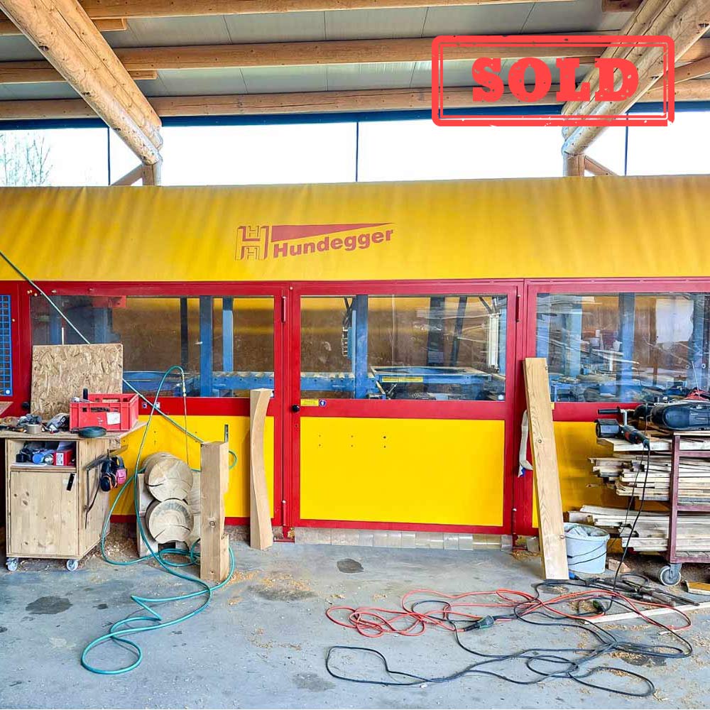
- Manufacturer: Krüsi
- Series: Lignamatic
- Build Year: 2010
- Availability: Dec 25 / Jan 26
